Have you recently noticed your Roomba started “circle dancing” or even reported the 9-beep error? Then this guide will help you to perform basic iRobot Roomba Repair at home. Please make sure to firstly go through all points in Roomba troubleshooting guide. The below instruction can be used for all 5xx and some 6xx Roomba models.
Warning!
The below guide voids product warranty and our website is not be responsible for any consequences caused by using the guide. The information is provided as is.
If your iRobot Roomba is till covered by warranty, we strongly recommend to firstly check with an authorized service centre.
What you will need
First: a basic understanding of how to solder.
Second: Infrared Emitters and Detectors
Please proceed with caution!
Tools
- Solder iron/gun
- Phillips screw driver
- Flat head screw driver.
- Tweezers.
- Needle Nose Pliers
- Multimeter or test lamp.
How to repair iRobot Roomba
- Remove the dust bin.
a) Remove the 4 screws from the bottom of the Roomba.
b) Remove the screw from the bottom brush.
c) Remove the brush by lifting straight up. It might need a little wiggle. - Remove the battery.
- Unscrew the 10 screws shown along the bottom edge of the bumper.
- Remove bumper edge.
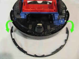
- Carefully remove the bumper.
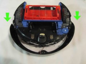
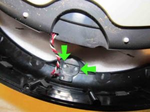
- Unscrew the 2 screws holding the virtual wall sensor, pay close attention not to lose the transparent half, it will fall out.
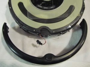
- Remove the front bumper completely.
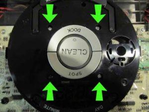
- Turn the Roomba so its top side is UP
a)Lift up the decorative cover.
b)The plate is held with clasps, pry from the bin area and move around.
c)Pry on the clasps with a screwdriver to release (if needed).
d)The handle needs to be lifted and the plate removed at an angle.
Some 530 machines may have one fewer layer of decoration.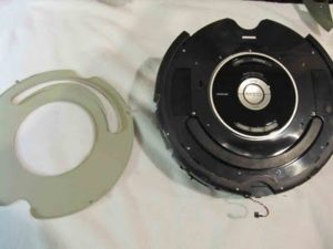
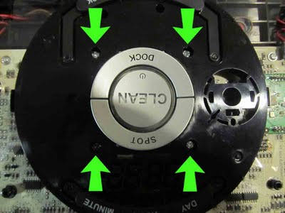
- Remove 11 screws of the top cover.
The screw below the words “SMALL” is smaller the the other 10 screws.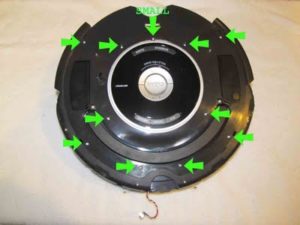
- Press in the button area with your thumbs and remove the cover straight up.
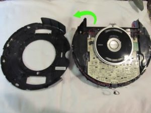
- Remove the buttons escutcheon plates.
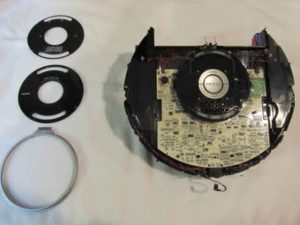
- Unscrew the 4 screws shown.
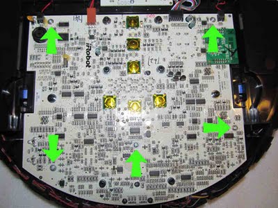
- Now you can see the Main Processing Board.
a) Disconnect the 4 rear connectors.
b) Each will only fit in its corresponding connector. No worries when re-assembling.
Some 530 machines may only have 3 instead of 4 connectors.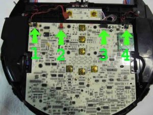
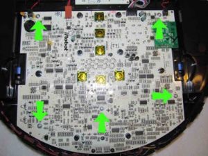
- Unscrew the 5 screws shown, that secure the Main Processing Board.
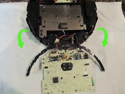
- Flip the Main Processing Board vertically towards the front of the Roomba as shown.
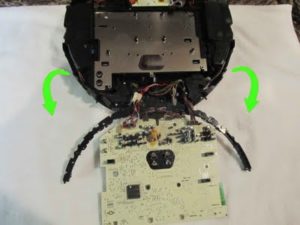
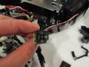
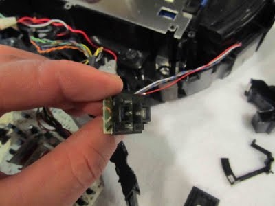
- Now the Bumper Sensor Housing can be seen.
a) The Sensors Housing are not universal, each is a different size and shape.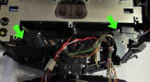
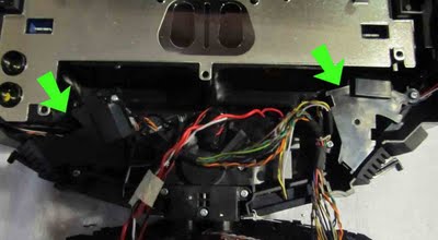
- Unscrew the 2 screws shown holding each Sensor Housing to the Roomba
- Remove the rubber dust cover as shown.

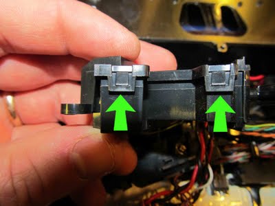
- Use a wide but thin blade screwdriver to release each of the 4 clasps on the top cover of both sensors housings.
a) Twist the screwdriver gently, BE CAREFUL Only a minimal amount of movement will release each clasp.
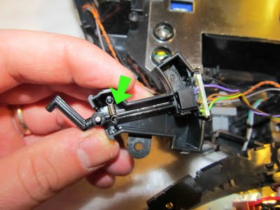
- After you removed the Sensor Housing cover, release and remove the actuating lever spring.
a) Needle Nose Pliers are useful in this task.
b) Spring in.
c) Spring out.
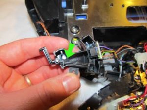
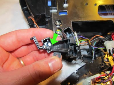
- Pulling straight up, the lever and the IR Sensor Board will come out.
a) Separate each.
b) Watch for the metal hinge rod, when re-assembling this needs to go back on the same side.
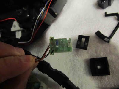
- Remove the IR Sensor Board Plastic Protective Shield.
a) Use Needle Nose Pliers or a Flat Head Screw Driver.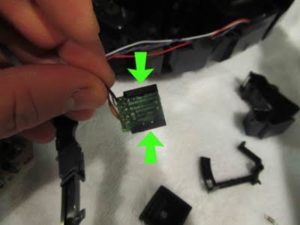
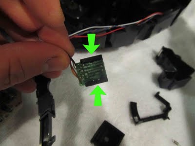
- Use the photo to reference the location of each sensor.
a)The Photo Transistor (NEW RED) is proximal (Closest) to the IR Sensor Wires
If its the original Sensor it should have a blue dot on the top.
b)The Photo Emitter (NEW YELLOW) is distal (Farthest) from the wires.
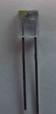
c)Both new sensors need to be oriented so that the bubble on the front is facing each other.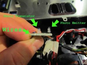

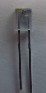
- FRONT FACE of EMITTER, NOTICE the bubble. This must face the other sensor.
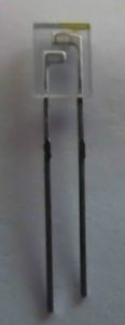
- BACK of EMITTER. NOTICE there is NO bubble.
- Unsolder the old EMITTERS. I don’t worry about getting all of the old solder off. Use needle nose pliers to put a little back pressure on one sensor at a time while heating the solder. Go back an forth heating each post until the sensor comes lose. Do this for all 2 EMITTERS. Next cut each post on the new sensors with wire cutters. Orient the EMITTERS, referencing the photo above and also making sure the bubble on the front is facing the other sensor. Push the new EMITTER through the holes, apply heat from the solder gun if they don’t slide right in. Solder each post to the board.
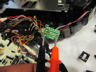
- Before you button everything up, use a multimeter or test lamp to test that you have continuity from the new sensor through the board to the corresponding wire. Do this by touching one test lead to sensor post and touch the other to the corresponding bare wire on the back. Do this for each wire.


Re-assembly – assemble all parts in reverse order.
- Put IR Sensor Board Plastic Protective Shield back on.
- Put IR lever and the IR Sensor Board back into Sensor Housing.
- Attach the spring.
- Snap the Sensor Housing Cover back on.
- Slide rubber dust boot back on.
- Screw both sensors back down.
a) Do the above 6 steps for both right and left bump sensor. - Flip Main Processing Board back over.
Make sure all wires are in there place and not getting pinched. - Screw the 5 screws back down.
- Connect the 4 rear Main Processing Board connectors.
- Screw in the 4 screws on the button plate.
- Put back the 3 button escutcheon plates.
- Place the main cover back on.
- Screw the 11 screws on the main cover. Paying attention to the smaller screw and its location.
- Replace the decorative top cover.
- Screw the virtual wall sensors 2 screws back in to the bumper.
Take care to put it back in correctly with the transparent half. - Slide the bumper back on, taking care that it is aligned properly.
- Screw the 10 screws holding the bumper cover edge back on.
The bumper can be tricky to get aligned properly take your time and do it right once. - Replace the battery.
- Place the bottom back on.
a) Screw the 4 screws back in
b) Replace the Corner Brush
c) Screw the corner brush back in, be careful this screw can strip easily. - Replace the dust bin.
- Cross your fingers.
If you tested with a multimeter or test lamp this step is not necessary. - TA-DA. Like new. THANK YOU.
Hi, how long it’s usually take?